Integrated Multi-fidelity Structural Optimization for UAV Wings
Revolutionizing UAV Wing Design Through Integrated Multi-Fidelity Optimization
The aerospace industry continually seeks innovation to enhance efficiency and performance. In Unmanned Aerial Vehicle (UAV) design, optimizing wing structures is paramount. The study, “Integrated Multi-Fidelity Structural Optimization for UAV Wings” and its associated DOI reference, explores advanced methodologies to achieve this goal by integrating low and high-fidelity optimization techniques.
Introduction to Multi-Fidelity Optimization
Multi-fidelity optimization combines low-fidelity methods for rapid prototyping with high-fidelity simulations for precise analysis. This approach balances computational efficiency and accuracy, ensuring optimal structural performance.
Key Advantages:
- Efficiency: Accelerates design iterations using low-fidelity simulations.
- Precision: Refines promising designs through high-fidelity tools like Finite Element Analysis (FEA).
- Innovation: Supports the development of lightweight, high-strength materials.
The Case Study: LSU-02 NGLD UAV
The research focuses on the LSU-02 NGLD, a UAV designed for maritime surveillance with a maximum range of 350 km and a payload capacity of 21 kg. The primary goal was to reduce wing weight while maintaining structural integrity.
Wing Materials
- Base Materials: Aluminum alloys (Al7075) and composite materials (E-glass and epoxy).
- Optimized Materials: Shift to Al2024 and epoxy carbon fiber for improved performance.
Optimization Methodology
1. Low-Fidelity Analysis
- Utilized for rapid prototyping and initial evaluations.
- Tools like XFLR5 enabled broad exploration of aerodynamic configurations.
2. High-Fidelity Analysis
- Conducted using ANSYS Composite Pre/Post (ACP) and Fluent for aerodynamics and structural analysis.
- Evaluated parameters like deformation, stress, strain, and buckling under operational conditions.
3. Material Parameterization
- Investigated laminate orientations (0°, 45°, 90°) and material properties.
- Stiffness matrices and transformation equations evaluated composite performance.
Key Findings
Optimized Configurations
The study evaluated nine material combinations. Notable results include:
- Epoxy Carbon Fiber with Al2024 Spar: Offered the best balance of weight, deformation, and safety.
- Epoxy S Glass with Al6061 Spar: Slightly lower stiffness but improved cost efficiency.
Weight and Safety Improvements
- Weight Reduction: Optimized wings weighed 3.53 kg, a 1.27% reduction compared to the base design.
- Factor of Safety: Increased from 1.665 to 1.875, ensuring enhanced reliability.
Aero-Structural Analysis
Flutter and Buckling Evaluations
- Flutter Analysis: Critical flutter speeds exceeded operational limits, ensuring stability.
- Buckling Analysis: Enhanced resistance under compressive forces, meeting safety standards.
Static and Dynamic Performance
The integration of winglets reduced vortex-induced drag, improving aerodynamic efficiency. Figures demonstrated notable reductions in deformation and stress concentrations.
Applications and Implications
1. Industry Impact
The methodology presents a scalable framework for UAV manufacturers, applicable to diverse aerospace designs.
2. Future Research
Opportunities include integrating machine learning for predictive modeling and exploring advanced composites like graphene-infused laminates.
3. Broader Benefits
- Energy Efficiency: Reduced weight translates to lower fuel consumption.
- Extended Lifespan: Enhanced structural integrity minimizes maintenance needs.
Conclusion
This study exemplifies the transformative potential of integrated multi-fidelity optimization in UAV design. By leveraging advanced materials and simulation techniques, engineers can achieve lightweight, robust, and efficient wings tailored for specific applications. As UAVs continue to play a critical role in surveillance, logistics, and beyond, such innovations will drive the next generation of aerospace engineering.
Tags
- UAV Optimization
- Multi-Fidelity Analysis
- Aerospace Engineering
- Structural Optimization
- Composite Materials
- Finite Element Analysis
- UAV Design

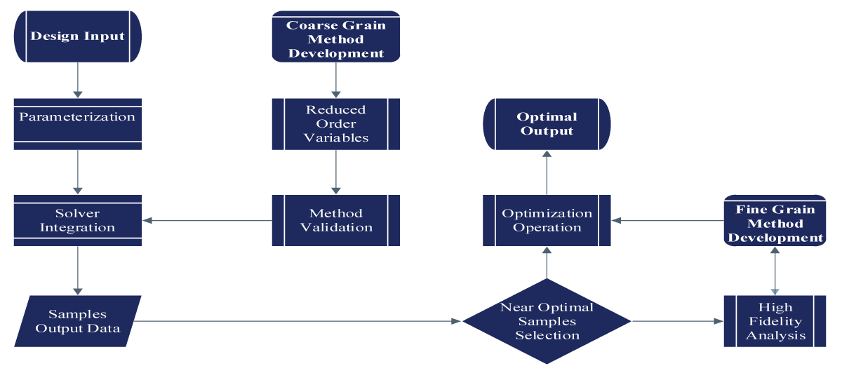
Figure 1: Methodology Demonstration

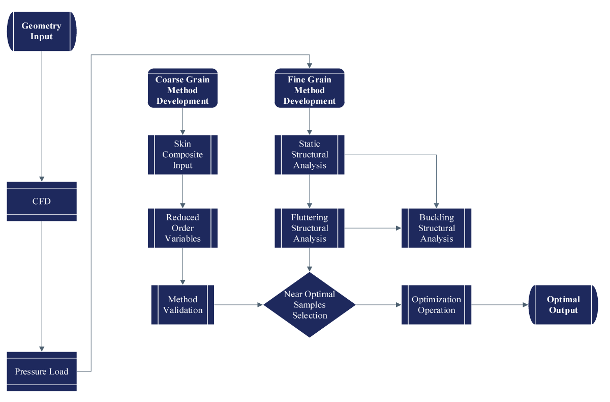
Figure 2: Structural Methodology Application Flowchart

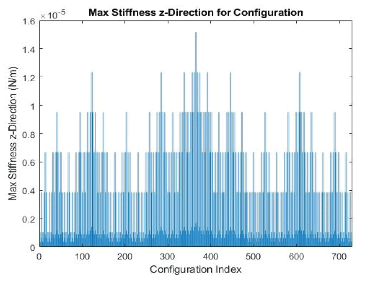
Figure 3: Computational Stiffness Value for 6-Layer Configuration

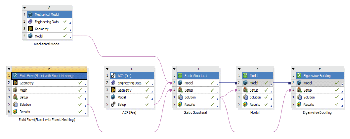
Figure 4: Flow Chart for Aero-Structural Analysis

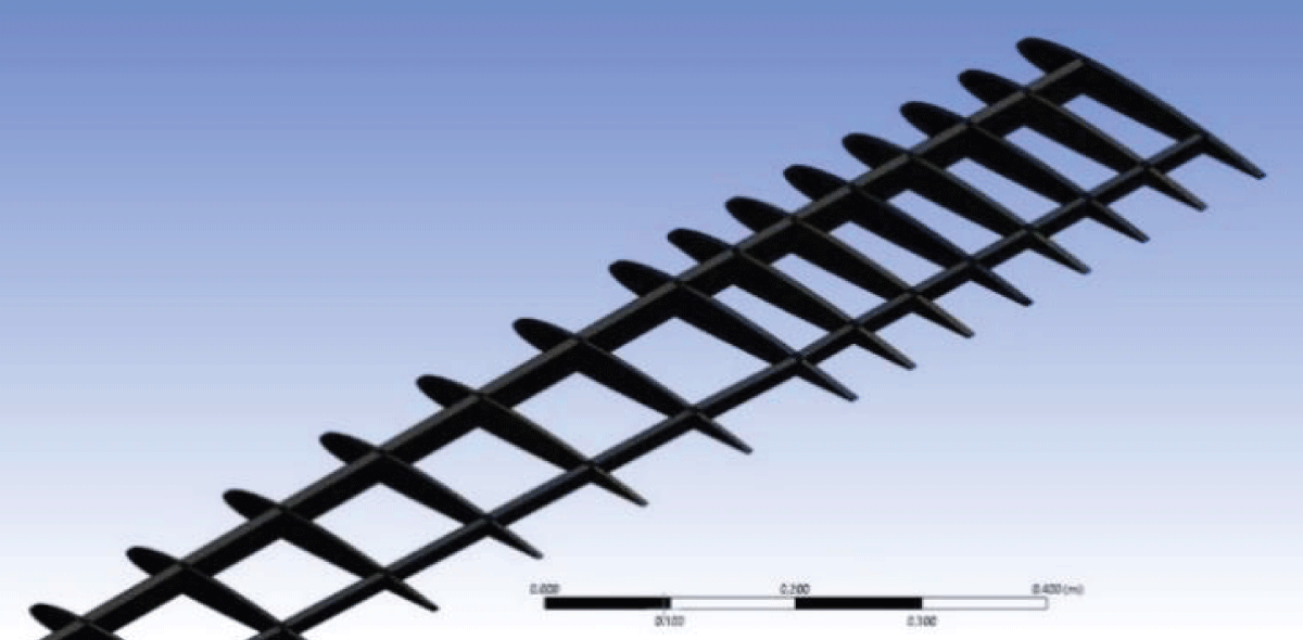
Figure 5: Rib and Spar Meshing on Mechanical Design

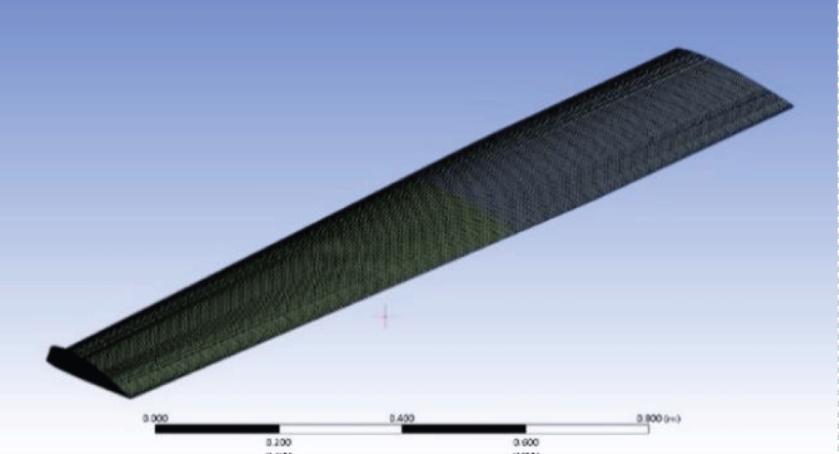
Figure 6: Skin Coupled Meshing for Skin, Rib, and Spar

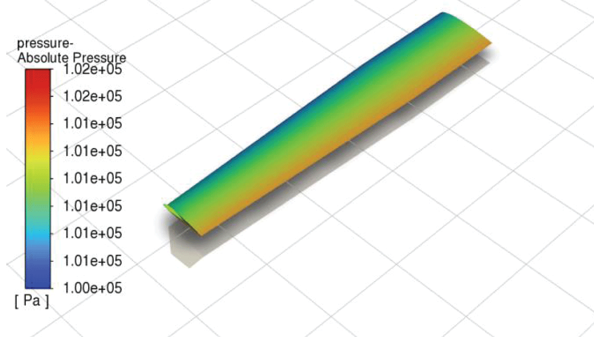
Figure 7: Pressure load distribution along the wing's lower surface

This is the heading
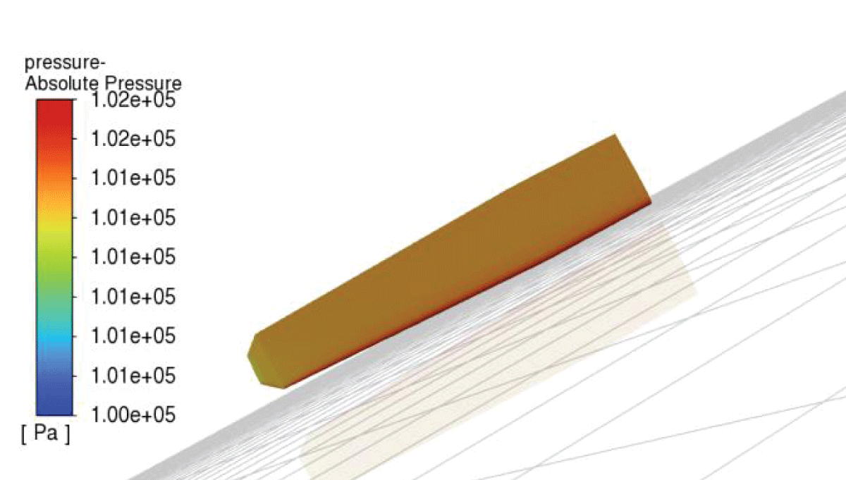
Figure 8: Pressure load distribution along the wing upper surface