Investigation of Lateral Vibrations in Turbine-generator Unit 5 of the Inga 2 Hydroelectric Power Plant

Investigating Lateral Vibrations in Turbine-Generator Unit 5 of the Inga 2 Hydroelectric Power Plant

Hydroelectric power plants are critical to sustainable energy, but their efficiency and reliability can be hindered by mechanical challenges. A recent study examined the lateral vibrations in Turbine-Generator Unit 5 of the Inga 2 Hydroelectric Power Plant, highlighting significant deviations from international vibration standards.

Key Findings

The research utilized 12 proximity and eddy-current probes to measure vibrations across multiple planes of the turbine-generator. The data were analyzed using Dasylab and R software, revealing alarming vibration amplitudes exceeding permissible limits:

  • Upper Guide Bearing: Measured deviations of 0.7 ± 0.2 mm, compared to the standard 0.07 mm.
  • Pivot/Rotor: Exhibited 2.31 ± 0.72 mm, far surpassing the acceptable limit of 0.07 mm.
  • Lower Guide Bearing: Deviations reached 1.1 ± 0.21 mm, indicating potential alignment and structural issues.

Causes of Excessive Vibrations

The study attributed these deviations to multiple factors, including:

  1. Rotor Mass Imbalances: Misalignment of the rotor shaft relative to the axis of rotation.
  2. Component Wear: Degradation of bearings, coupling shafts, and seals.
  3. Hydraulic and Electrical Stresses: During water intake, turbine rotation, and load pickups, stresses exacerbate vibration levels.

Compliance Analysis and Implications

Statistical evaluations confirmed significant discrepancies between measured amplitudes and international vibration standards. This non-compliance highlights critical risks:

  • Efficiency Loss: Excessive friction and misalignment reduce energy output.
  • Structural Damage: Persistent vibrations accelerate wear on mechanical components.
  • Safety Hazards: Increased risks of failures threaten the operational integrity of the turbine.

Recommendations

To restore compliance and operational efficiency, the study suggests:

  1. Complete Realignment: Addressing shaft misalignment to stabilize the turbine axis.
  2. Component Upgrades: Replacing degraded bearings and seals.
  3. Monitoring Systems: Installing advanced sensors for continuous vibration analysis.

For further details, access the full study here or via its DOI link.

Tags:

  • Hydroelectric Power
  • Vibration Analysis
  • Turbine Generator Maintenance
  • Inga 2 Power Plant
  • Mechanical Engineering

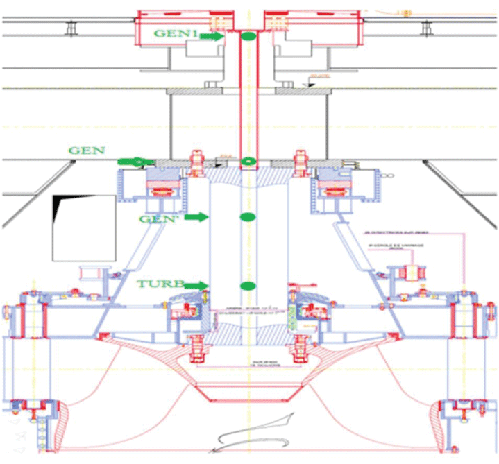
Figure 1: Sensor location on each measurement plane [16].

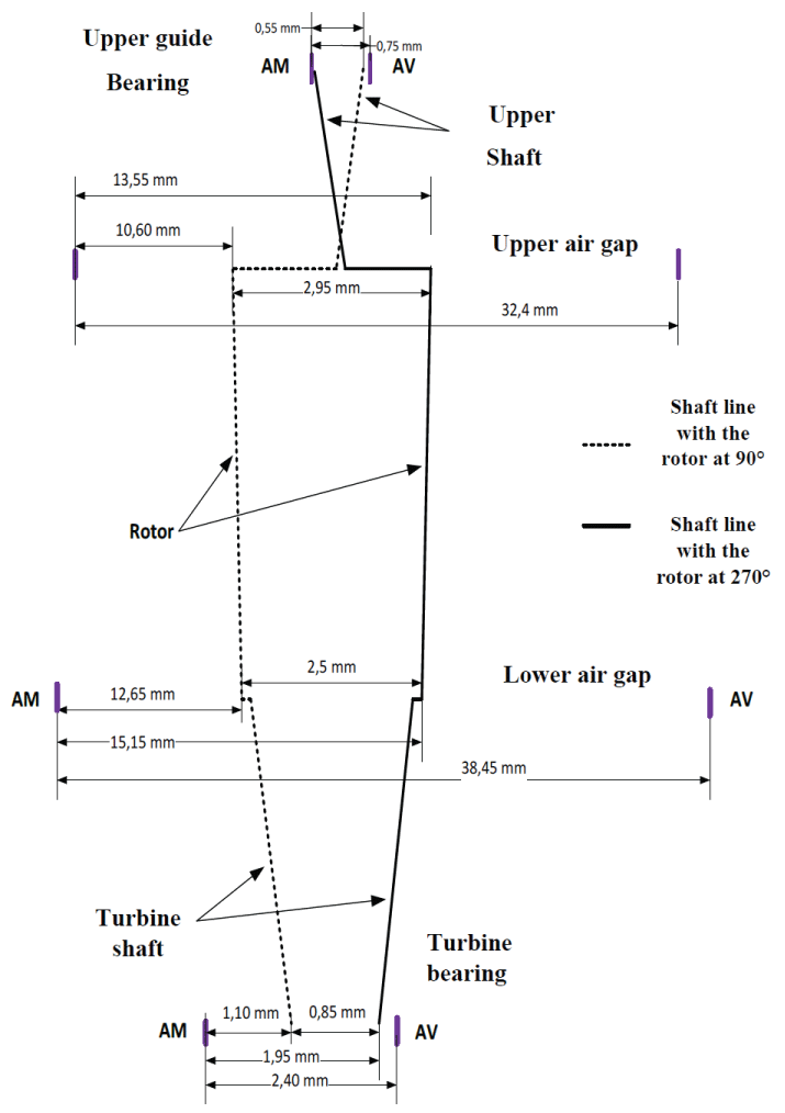
Figure 2: Shaft lines along the upstream-downstream axis.

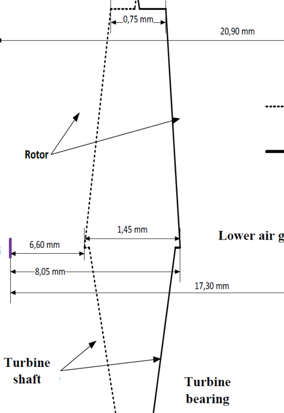
Figure 3: Shaft lines along the left bank-right bank axis.

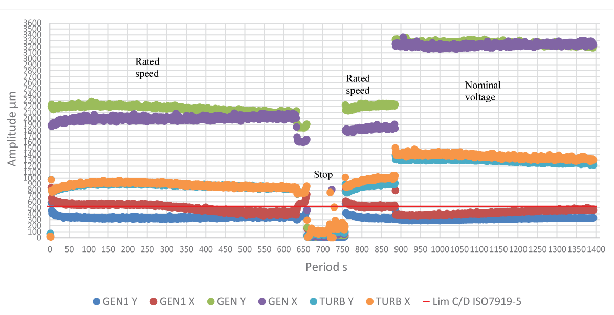
Figure 4: Evolution (cloud) of the overall (peak-to-peak) displacement values for the last two tart-ups (06/07).

Leave a Reply

Your email address will not be published. Required fields are marked *